Research Article | | Peer-Reviewed

Research on Experimental Teaching Methods for Circuit Analysis Based on Multisim Simulation Software

Received: 20 January 2026     Accepted: 2 February 2026     Published: 20 February 2026
Views:       Downloads:
Abstract

To address the persistent challenges in the “Circuit Analysis” laboratory course-characterized by perfunctory preparation, superficial practice, and a lack of innovation—this paper proposes and implements a blended teaching reform centered on “virtual-real integration and competency orientation.” The new framework systematically restructures the instructional process into three integrated stages: pre-class, in-class, and post-class. Taking the experiment on “Measuring Active and Reactive Power in Three-Phase Circuits” as a case study, the model deeply integrates the Rain Classroom smart tool with the Multisim simulation platform, creating a closed-loop pedagogical cycle of “simulation-based preparation, hands-on exploration, and design-oriented extension.” The pre-class phase uses Multisim for theoretical visualization and preliminary inquiry. The in-class phase involves comparing simulation results with physical circuit measurements to deepen understanding of practical engineering issues. The post-class phase assigns open-ended design tasks to foster problem-solving and innovative thinking. This reform effectively transforms the traditional teacher-led model into a student-centered paradigm of active inquiry and application. The results demonstrate that this approach significantly enhances teaching quality and learning outcomes, while also establishing a replicable and scalable new paradigm for experimental education that provides a practical solution to common challenges in foundational engineering courses.

Published in Education Journal (Volume 15, Issue 1)
DOI 10.11648/j.edu.20261501.13
Page(s) 18-24
Creative Commons

This is an Open Access article, distributed under the terms of the Creative Commons Attribution 4.0 International License (http://creativecommons.org/licenses/by/4.0/), which permits unrestricted use, distribution and reproduction in any medium or format, provided the original work is properly cited.

Copyright

Copyright © The Author(s), 2026. Published by Science Publishing Group

Keywords

Virtual-Real Integration, Competency Orientation, Blended Teaching, Circuit Analysis Laboratory, Multisim

1. Introduction
As a cornerstone foundational course for automation and electrical engineering disciplines, the quality of “Circuit Analysis” instruction directly impacts the learning outcomes of subsequent advanced courses. It is a critical phase for building students’ knowledge frameworks, honing their practical skills, and fostering innovative thinking. However, the widely adopted “theory+lab” teaching model exhibits significant shortcomings . The theoretical component, with its highly abstract nature and tedious analytical processes, often proves unengaging for students. Concurrently, the laboratory segment, hampered by outdated content and rigid methodologies, fails to effectively ignite students’ passion for learning, resulting in limited development of their practical abilities and innovative capacities.
The core dilemmas plaguing the current laboratory instruction can be summarized as follows:
Rigid Content, Insufficient Challenge: Experiments are predominantly confined to simple verifications of classical theories, lacking the depth and breadth necessary to cultivate students’ analytical and problem-solving skills when faced with complex circuits .
Passive Model, Stifled Innovation: The traditional pedagogical approach is teacher-dominated, relegating students to a passive, “cookbook” style of operation. This leaves minimal room for autonomous inquiry and deep reflection, significantly diminishing the educational effectiveness.
2. Methods
To address the aforementioned challenges, we propose a teaching reform plan centered on the core principles of “Virtual-Real Integration and Competency-Orientation.” This plan systematically restructures the teaching process into three distinct phases—“Pre-class, In-class, and Post-class”—while deeply integrating both online and offline, as well as verification-based and design-based, learning modalities .
The core of this reform is the introduction of advanced virtual simulation technologies, such as Multisim, and the restructuring of the teaching workflow as follows:
Pre-class (Virtual Pre-study, Theory First): Instructors assign experimental tasks via online platforms like Rain Classroom. Students are required to independently use Multisim software to build simulation circuits, complete the experiment, and draw preliminary conclusions before the physical lab session.
In-class (Virtual-Real Comparison, Deepening Cognition): In the laboratory, students construct and test the physical circuit according to the experiment requirements, recording real-world data. They then compare and analyze these empirical results against their pre-class simulation findings to investigate the causes of any discrepancies.
Post-class (Design Extension, Competency Transfer): Instructors assign more challenging, design-oriented tasks related to the experiment’s content. Students must utilize Multisim for circuit design and parameter optimization after class, submitting their final designs to an online platform for instructor feedback and evaluation .
This reform is grounded in the characteristics of the mobile intelligent learning era and the learning needs of university students, while being closely aligned with the institution’s educational mission and the program’s unique features. It emphasizes a profound integration of “online and offline” and “theory and practice,” achieving a “virtual-real combination” in teaching through the adoption of simulation technology. Furthermore, by using real-world engineering problems as a catalyst, it guides students to proactively tackle complex challenges, significantly enhancing the course’s level of challenge and higher-order learning . This approach fully embodies the course’s scientific rigor and innovative spirit, with the ultimate goal of cultivating outstanding talent equipped with a solid theoretical foundation, exceptional practical skills, and a capacity for continuous innovation.
2.1. Verification-Based Experiment
Taking the “Three-Phase Circuit Power Measurement” experiment as a case study, we will detail the entire implementation process of an experimental project based on Multisim simulation software, covering both verification and design components.
Pre-class: Through the Rain Classroom online learning platform, instructors assign a pre-study task for the upcoming lab. Students are required to use the Multisim software tool to build a simulation model of a three-phase asymmetric circuit. Utilizing the software’s built-in modules for voltmeter, wattmeter, and ammeter, they measure the active power of the three-phase circuit . They then perform power calculations using the theoretical formulas for active power in three-phase circuits learned in lectures. Finally, students compare and analyze the calculated results against the simulation measurements and upload their findings to the Rain Classroom platform.
In-class: Students proceed to the physical lab workstations to wire the three-phase circuit as outlined in the pre-study task, read the experimental results from the physical instruments, and complete the integration of “Theory-Simulation-Experiment.”
Post-class: To further extend and build upon this project, students are tasked with measuring and analyzing the reactive power in both three-phase symmetric and asymmetric circuits. This process encourages students to continually connect their lab work with theoretical concepts, fostering a deeper understanding. It familiarizes them with simulation tools, actively guides them toward independent thinking, and enhances their critical analysis skills.
2.1.1. Task Publication
The pre-class task is released on the Rain Classroom online learning platform as follows: For the unbalanced three-phase circuit shown in Figure 1, the RMS phase voltage of the three-phase source is 220 V with a frequency of 50 Hz. The impedances are Zl = 1 + j2 Ω, Z1 = 1936 Ω, Z2 = 1936 + j3184 Ω, and Z3 = 1936 + j4710 Ω. Students are required to calculate the total power of the three-phase circuit and then build a corresponding simulation model using Multisim for verification.
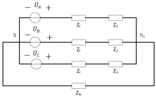
Figure 1. Diagram of an Unbalanced Three-Phase Circuit.
2.1.2. Theoretical Analysis
Methods for measuring the active power of a three-phase circuit include the single-wattmeter method, the two-wattmeter method, and the three-wattmeter method. The single-wattmeter method can be used when the circuit is balanced and connected in a three-phase, four-wire configuration. For an unbalanced three-phase circuit with a four-wire connection, only the three-wattmeter method is suitable. For any three-phase, three-wire circuit, whether balanced or unbalanced, the two-wattmeter method is used. The circuit in this experiment is an unbalanced, three-phase, four-wire circuit; therefore, the three-wattmeter method is adopted. Its wiring method is illustrated in the figure below .
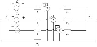
Figure 2. Connection Diagram for Three-Wattmeter Power Measurement.
The formulas for calculating the active power of a three-phase circuit are as follows:
P=PA+PB+PC=UAIAcosφA+UBIBcosφB+UCICcosφC(1)
PA=UAIAcosφA=UAUAIA=220×2201939=25W(2)
PB=UBIBcosφB=UBUBZBcosφB=220×22019362+31842×0.519=6.73W(3)
PC=UCICcosφC=UCUCZCcosφC=220×22019362+47102×0.38=3.61W(4)
P=PA+PB+PC=25W+6.73W+3.61W=35.34W(5)
2.1.3. Building the Simulation Model
In the Multisim simulation environment, construct the simulation model based on the circuit schematic. Configure the simulation parameters in the model according to the values provided in Table 1. Specifically, the RMS phase voltage of the three-phase source is set to 220 V, and the line impedances and three-phase loads are converted into their equivalent resistance and inductance values. The completed simulation model is shown in Figure 3.
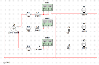
Figure 3. Active Power Measurement in a Three-Phase Circuit.
Table 1. Parameter Table of Experimental Circuit Component.

Parameter

Set Value

RMS Source Voltage / V

220

Line Inductance / H

6.4

Line Resistance / Ω

1

Phase A Load Resistance / Ω

1936

Phase B Load Capacitance / μF

1

Phase B Load Resistance / Ω

1936

Phase C Load Inductance / H

15

Phase C Load Resistance / Ω

1936

2.1.4. Simulation Result Analysis
In Multisim, click the simulation button and then double-click each wattmeter to display the active power of each phase load. The results are shown in Figure 4.
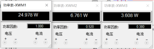
Figure 4. Simulation Results of Power Measurement in a Three-Phase Circuit.
Figure 4 shows that the power and power factor are different for each of the three-phase loads. Phase A is a purely resistive load without series inductance or capacitance, so its terminal voltage is close to the rated 220 V. As a result, its power is about 25 W and its power factor is 1. In contrast, Phases B and C have series capacitors and inductors, causing the voltage across the lamps to differ from the rated voltage. This results in a power much lower than the rated power and a power factor of less than 1. The total circuit power is 35.347 W, which agrees with the theoretical calculation.
2.2. Design-Oriented Experiment
In practical three-phase circuits, not all wiring configurations are of the three-phase four-wire type. For unbalanced circuits with a three-phase three-wire connection, the three-wattmeter method cannot be used to measure the load’s active power. The reason is that the three-wattmeter method requires connecting the voltage coil of each wattmeter to the neutral line. To further enhance students’ mastery of proper wattmeter wiring and their understanding of wye (Y) and delta (Δ) three-phase load connections, we pose the following research question based on the issue described above: How can one use wattmeters to measure active power in a three-phase three-wire circuit?
Students are required to build upon the foundational verification simulation by working in groups to conduct this design-oriented experiment. The experimental results must then be submitted to the online learning platform. The following section uses a three-phase three-wire Y-Y connected circuit as an example to illustrate the implementation process for this design-oriented experiment .
2.2.1. Principle of the Two-Wattmeter Method for Measuring Active Power
The wiring diagram for measuring active power in a circuit using the two-wattmeter method is shown in Figure 5. The total active power is calculated as: P=P1+P2=UACIAcosφ1+UBCIBcosφ2,where φ1=φ-30°φ2=φ+30°.
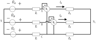
Figure 5. Schematic Diagram of the Two-Wattmeter Method for Measuring Active Power.
2.2.2. Building the Simulation Model
Based on the previous simulation model, remove the neutral wire to reconfigure the circuit as a three-phase three-wire system. As shown in Figure 6, connect Wattmeter 1 across Phase A and Phase C, and connect Wattmeter 2 across Phase B and Phase C. Run the simulation; the sum of the readings from the two wattmeters will be the total power of the three-phase load .
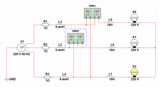
Figure 6. Circuit Diagram for Measuring Three-Phase Load Power Using the Two-Wattmeter Method.
2.2.3. Simulation Results
After running the simulation, the power readings are obtained as shown in Figure 7. Since the load is balanced, the power factor angle of each phase load is 68°. As can be seen from Figure 8, the active power of the balanced three-phase circuit is 10.836 W. The reason the measured power on Wattmeter 2 is negative is that the load’s power factor angle is 68°, resulting in cosφ2=cos30+68°=-0.193, which makes P₂ negative. However, this does not affect the measurement of the total power in the three-phase circuit.
Through this design-oriented experiment, students can further master the use of wattmeters and the associated precautions, while also deepening their understanding of active power measurement methods.
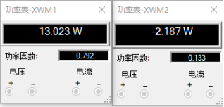
Figure 7. Measurement Results from the Wattmeters.
2.3. Handling of Differences Between Simulation Results and Hardware Measurement Results
In the three-phase circuit power measurement experiment, there are objective deviations between simulation results and hardware measurement results, which need to be explained from two aspects: "analysis of difference causes" and "systematic processing methods":
2.3.1. Analysis of Difference Causes
By comparing the simulation data and hardware measurement data of the verification experiment (three-phase four-wire unbalanced circuit) and the design-oriented experiment (three-phase three-wire balanced circuit), it is found that the differences mainly stem from the following three categories:
Differences in non-ideal characteristics of components: Ideal components are adopted in the Multisim simulation model (e.g., resistors without temperature drift, inductors without magnetic leakage, and power supplies without internal resistance). However, actual components in hardware experiments have inherent errors (e.g., the deviation between the nominal value and actual value of resistors is ±5%, inductance coils have parasitic resistance, and capacitor aging leads to capacitance offset).
Measurement system errors: Instruments such as wattmeters and voltmeters used in hardware experiments have limitations in accuracy class (the accuracy class of instruments used in this experiment is Class 0.5), resulting in inherent measurement errors. In contrast, the measurement modules in the simulation software have no system errors, and the data reading accuracy can reach 3 decimal places.
Environmental and operational interference: In hardware experiments, factors such as power supply voltage fluctuation (±2V), electromagnetic interference in the laboratory, and wiring contact resistance can cause fluctuations in measured data. The simulation environment is an ideal interference-free scenario with higher data stability.
2.3.2. Difference Processing Methods
To reduce the impact of differences on experimental conclusions, a systematic processing scheme of "source calibration + data correction + error attribution" is adopted:
Hardware calibration: Before the experiment, the actual parameters of all components are measured (e.g., using a high-precision multimeter to measure the actual values of resistors and inductors). The measured parameters are used to replace the ideal parameters in the simulation model, and the simulation is re-conducted to make the simulation model more consistent with the hardware experiment scenario;
Data correction: For instrument system errors, correction values are calculated according to the instrument accuracy class (e.g., the maximum allowable error of a Class 0.5 wattmeter is ±0.5% × full scale), and the measured data are corrected.
2.4. Diversified Evaluation Mechanism
The traditional experimental evaluation model is mostly confined to single-dimensional assessments such as the standardization of experimental operations and the completeness of experimental reports. Although this model can reflect students' abilities of independent learning and absorption of new knowledge to a certain extent, it has significant shortcomings including a single evaluation subject, a one-sided assessment perspective, and susceptibility to subjective factors during the scoring process. Consequently, it is difficult to comprehensively and objectively measure students' overall competency level.
To address this issue, this study constructs a trinity diversified experimental teaching evaluation system of "student self-evaluation, group peer evaluation, and teacher evaluation" in the teaching reform. Breaking through the traditional single evaluation framework, this system adopts a multi-subject and multi-dimensional approach. It not only focuses on the standardization and proficiency of students' experimental operations but also emphasizes the assessment of their engineering problem-solving abilities, innovative thinking, and teamwork literacy, thereby achieving a comprehensive insight and scientific evaluation of students' comprehensive engineering capabilities. The specific evaluation criteria are shown in Table 2.
Table 2. Circuit Experiment Evaluation System.

Evaluation Category

Evaluation Item

Evaluation Method

Weight

Formative Evaluation

Awareness & Attitude

Offline teacher scoring + online system scoring

5%

Preview Effect

Online system scoring

5%

Experimental Skills

Teacher scoring + student self-evaluation + peer evaluation

20%

Application & Extension

After-class extended experiments, teacher scoring

20%

Summative Evaluation

Experimental Report

Teacher scoring

50%

3. Conclusions
This paper addresses the long-standing challenges in the experimental teaching of “Circuit Analysis”—namely, perfunctory pre-class preparation, superficial hands-on practice, and a lack of innovative post-class extension. It systematically proposes and implements a blended teaching reform model based on an integrated “pre-class, in-class, and post-class” framework. Taking the experiment on “Measuring Active and Reactive Power in Three-Phase Circuits” as a specific case study, this model deeply integrates the Rain Classroom smart teaching tool with the Multisim virtual simulation platform, constructing a three-stage pedagogical loop of “simulation-based preparation, hands-on exploration, and design-oriented extension.”
Through continuous practical exploration and teaching reform, phased achievements have been made in this course, with students' practical operation capabilities and engineering problem-solving skills significantly enhanced. In the first semester of the 2024-2025 academic year, the average score of the Circuit Analysis experiment course for 135 freshmen majoring in Automation was 62.3 points. In the first semester of the 2025-2026 academic year, after introducing Multisim simulation software-assisted teaching for 4 classes (140 students) of freshmen in this major, the average course score increased to 80.1 points. Two teachers in the research group were awarded the university-level "Good Teachers in Students' Minds" in 2025. In addition, teachers of the research group guided students to participate in the China Robot and Artificial Intelligence Competition, winning 1 national second prize, 1 national third prize, 2 provincial first prizes, and 4 provincial third prizes. Both the quality of talent training and competition achievements have achieved steady improvement.
Practice has proven that this model effectively transforms the traditional “teacher-demonstration, student-imitation” paradigm into a student-centered model of “active inquiry, deep thinking, and innovative application.” In the pre-class phase, Multisim simulation tasks allow students to visualize abstract theories, enabling them to enter the laboratory with questions and preliminary experience, thus achieving a shift from passive reading to active inquiry. During the in-class phase, building on their simulation preparation, students can conduct hands-on operations more confidently. Guided by the instructor, they deepen their understanding of practical engineering issues—such as the non-ideal characteristics of real components and measurement errors—by comparing discrepancies between simulated and measured results, thereby internalizing and consolidating their knowledge. The post-class phase, featuring open-ended design tasks (like measuring power in a three-phase three-wire system), further drives students to apply their knowledge and engage in autonomous creation, effectively cultivating their engineering design, problem-solving, and innovative thinking skills.
In summary, this teaching reform has not only significantly enhanced the instructional quality of the “Circuit Analysis” lab course and improved student learning outcomes but, more importantly, has established a new, replicable, and scalable paradigm for experimental education. This paradigm deeply integrates information technology with teaching practice and embeds engineering thinking training throughout the entire instructional process, providing a practical and feasible solution to the common challenges facing foundational engineering laboratory courses.
Abbreviations

RMS

Root Mean Square

Author Contributions
Jiangpeng Li: Methodology, Formal analysis, Writing – original draft, Writing – review & editing
Xiaoliu Yang: Writing – review & editing
Funding
This work is supported by the 2025 Educational Teaching Research and Reform Project of Maotai Institute "Research on the Construction of Knowledge Graph and the Integration Mechanism of Ability Graph in Curriculum Groups from the Perspective of Engineering Certification - A Case Study of Process Control Curriculum Group" (mtxyjg2025006),
Conflicts of Interest
The authors declare no conflicts of interest.
References
[1] Qiaolan WANG. “Teaching Reform and Practice of ‘Circuit Analysis Laboratory’ Assisted by Virtual Simulation” [J]. Industrial Control Computer, 2025, 38(10): 135-137.
[2] Longyun JIANG. “Application of Simulink Simulation in the Basic Experimental Teaching of Circuit Analysis” [J]. Journal of Tonghua Normal University, 2025, 46(06): 134-139.
[3] Kuwatbaike Mamuti, Iliyar Jiamuhaimaiti, Huoja Tuohetasen. “Exploration on the Application Effect of Multisim Simulation Software in the Basic Experimental Teaching of Circuit Analysis” [J]. Journal of Ili Normal University (Natural Science Edition), 2020, 14(04): 67-74.
[4] Lingmin WU, Jiawei LI. “Simulation Analysis of Three-Phase Circuits Based on Multisim 10” [J]. PC Programming Skills & Maintenance, 2020, (07): 153-156+164.
[5] Wen ZHOU, Xie ZHOU. “Fault Analysis of Three-Phase AC Circuit Experiments Based on Multisim” [J]. Industrial Control Computer, 2020, 33(04): 147-148.
[6] Nannan LU, Yanjing SUN, Yanfen WANG, et al. “Simulation Analysis of Three-Phase Circuits Based on Multisim” [J]. Experiment Science and Technology, 2019, 17(02): 18-21+26.
[7] Haiyan LIU, Shuyi ZHEN, Jiadong HUANG, et al. “Simulation Analysis of Three-Phase Circuits Based on Multisim” [J]. Modern Electronics Technique, 2005, (19): 101-103+106.
[8] Xiufen W, Shengyi Y, Jiang P. Application of Multisim in Teaching Reform of Digital Circuit Experiment [J]. Education Reform and Development, 2025, 7(2): 67-76.
[9] Ma Y. Teaching Reform and Practice of Sensor Course Based on Arduino+NI Multisim [J]. Journal of Higher Vocational Education, 2024, 1(2):
[10] Li L, Meng L, Wang F. Design and simulation of frequency divider circuit based on multisim [J]. E3S Web of Conferences, 2021, 268 01058.
[11] Li P. Electronic Circuit Teaching Aided by Multisim Virtual Simulation Software [J]. Advanced Materials Research, 2014, 3160 (933-933): 703-707.
[12] Su J. The Application of Multisim Simulation Platform in Teaching and Scientific Research of Mixed-Signal Circuit [C]// 2017:
[13] National instruments multisim 11 simplifies circuit simulation for teaching and design [J]. Engineer, 2010, 11 JANUARY
[14] Licarião F A N, Pereira H V C D, Lauro R W. Simulated Experiments for Teaching Mutually-Coupled Circuits CAD Techniques Using Analytic and Finite Element Solutions [J]. Journal of Electromagnetic Analysis and Applications, 2017, 09 (11): 183-202.
Cite This Article
  • APA Style

    Li, J., Yang, X. (2026). Research on Experimental Teaching Methods for Circuit Analysis Based on Multisim Simulation Software. Education Journal, 15(1), 18-24. https://doi.org/10.11648/j.edu.20261501.13

    Copy | Download

    ACS Style

    Li, J.; Yang, X. Research on Experimental Teaching Methods for Circuit Analysis Based on Multisim Simulation Software. Educ. J. 2026, 15(1), 18-24. doi: 10.11648/j.edu.20261501.13

    Copy | Download

    AMA Style

    Li J, Yang X. Research on Experimental Teaching Methods for Circuit Analysis Based on Multisim Simulation Software. Educ J. 2026;15(1):18-24. doi: 10.11648/j.edu.20261501.13

    Copy | Download

  • @article{10.11648/j.edu.20261501.13,
      author = {Jiangpeng Li and Xiaoliu Yang},
      title = {Research on Experimental Teaching Methods for Circuit Analysis Based on Multisim Simulation Software},
      journal = {Education Journal},
      volume = {15},
      number = {1},
      pages = {18-24},
      doi = {10.11648/j.edu.20261501.13},
      url = {https://doi.org/10.11648/j.edu.20261501.13},
      eprint = {https://article.sciencepublishinggroup.com/pdf/10.11648.j.edu.20261501.13},
      abstract = {To address the persistent challenges in the “Circuit Analysis” laboratory course-characterized by perfunctory preparation, superficial practice, and a lack of innovation—this paper proposes and implements a blended teaching reform centered on “virtual-real integration and competency orientation.” The new framework systematically restructures the instructional process into three integrated stages: pre-class, in-class, and post-class. Taking the experiment on “Measuring Active and Reactive Power in Three-Phase Circuits” as a case study, the model deeply integrates the Rain Classroom smart tool with the Multisim simulation platform, creating a closed-loop pedagogical cycle of “simulation-based preparation, hands-on exploration, and design-oriented extension.” The pre-class phase uses Multisim for theoretical visualization and preliminary inquiry. The in-class phase involves comparing simulation results with physical circuit measurements to deepen understanding of practical engineering issues. The post-class phase assigns open-ended design tasks to foster problem-solving and innovative thinking. This reform effectively transforms the traditional teacher-led model into a student-centered paradigm of active inquiry and application. The results demonstrate that this approach significantly enhances teaching quality and learning outcomes, while also establishing a replicable and scalable new paradigm for experimental education that provides a practical solution to common challenges in foundational engineering courses.},
     year = {2026}
    }
    

    Copy | Download

  • TY  - JOUR
    T1  - Research on Experimental Teaching Methods for Circuit Analysis Based on Multisim Simulation Software
    AU  - Jiangpeng Li
    AU  - Xiaoliu Yang
    Y1  - 2026/02/20
    PY  - 2026
    N1  - https://doi.org/10.11648/j.edu.20261501.13
    DO  - 10.11648/j.edu.20261501.13
    T2  - Education Journal
    JF  - Education Journal
    JO  - Education Journal
    SP  - 18
    EP  - 24
    PB  - Science Publishing Group
    SN  - 2327-2619
    UR  - https://doi.org/10.11648/j.edu.20261501.13
    AB  - To address the persistent challenges in the “Circuit Analysis” laboratory course-characterized by perfunctory preparation, superficial practice, and a lack of innovation—this paper proposes and implements a blended teaching reform centered on “virtual-real integration and competency orientation.” The new framework systematically restructures the instructional process into three integrated stages: pre-class, in-class, and post-class. Taking the experiment on “Measuring Active and Reactive Power in Three-Phase Circuits” as a case study, the model deeply integrates the Rain Classroom smart tool with the Multisim simulation platform, creating a closed-loop pedagogical cycle of “simulation-based preparation, hands-on exploration, and design-oriented extension.” The pre-class phase uses Multisim for theoretical visualization and preliminary inquiry. The in-class phase involves comparing simulation results with physical circuit measurements to deepen understanding of practical engineering issues. The post-class phase assigns open-ended design tasks to foster problem-solving and innovative thinking. This reform effectively transforms the traditional teacher-led model into a student-centered paradigm of active inquiry and application. The results demonstrate that this approach significantly enhances teaching quality and learning outcomes, while also establishing a replicable and scalable new paradigm for experimental education that provides a practical solution to common challenges in foundational engineering courses.
    VL  - 15
    IS  - 1
    ER  - 

    Copy | Download

Author Information